what are you trying to accomplish again?


Ok and with no luck...
Just double check make sure I hooked up everything up right. Thanks.
I tried pics 3&4 which in this pic are the black/white and red/blue ones.

03 ES 5spd--Rota torque gloss black 17x8 et. 35--Hankook Ventus V12 evo 235/45/17--D2 coilovers--DC Sports STB--Intake--Brembo calipers--Powerslot Rotors--Stoptech Pads--SS brakes lines--35% tint--5k heads & 5k fogs--Alpine headunit--Kicker 400w amp--Alphasonix sub
what are you trying to accomplish again?
Lancer/EvolutionX Rotor Glow Paint
6g74 Forged Engine w/ hx40 turbo
Eclipse GT 5 spd swapped
Rotor Glow Galant
Daily Galant
OZ Edition Eclipse


Fixin the speedo, I have an 03 and I'm 5spd swapped.
03 ES 5spd--Rota torque gloss black 17x8 et. 35--Hankook Ventus V12 evo 235/45/17--D2 coilovers--DC Sports STB--Intake--Brembo calipers--Powerslot Rotors--Stoptech Pads--SS brakes lines--35% tint--5k heads & 5k fogs--Alpine headunit--Kicker 400w amp--Alphasonix sub
Whitegalant:
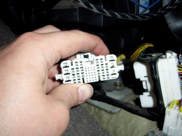
You have the right harness but read the wrong pins; pins 3 and 4 are the yellow/black(pin 3) and white gray(pin 4) on the harness in your picture (looking at the pic, it's on the LEFT side).
I had the same exact problem when i did the install, found out i was right the first time
make sure you solder the connections, splice connectors aren't the best, they didn't work for me the first time i installed the sensor.
here's a few pics for reference....
in this pic, the splice connections are on the correct wires (just didn't splice as properly as a solder connection would)
the red wire was connecting the 2 black/yellow wires from the sensor to the harness, while my green wire is connecting the black/blue wire from the sensor to pin 3 on the harness(white/gray). Ground you can put anywhere, mine is the ground next to the battery.
I'll try to get more pics tomorrow. My speedometer's been working for a few days, just gets a little jumpy every now and then, especially on right turns, probably cause i'm still using splice connections at the sensor side and solder connections at the harness side. :\
02 Mit. Galant 5 Spd -> 2010 Mit. Lancer Sportback 5 Spd -> (current) 2014 Mit Evo GSR 5 Spd
run1206's Rear Disc Tutorial
run1206's CF Hood Resurface Tutorial


OOOOO cool thanks Drew, where did you run your wire through the firewall? Any suggestions?
03 ES 5spd--Rota torque gloss black 17x8 et. 35--Hankook Ventus V12 evo 235/45/17--D2 coilovers--DC Sports STB--Intake--Brembo calipers--Powerslot Rotors--Stoptech Pads--SS brakes lines--35% tint--5k heads & 5k fogs--Alpine headunit--Kicker 400w amp--Alphasonix sub
Roman cut a hole for me when we did the swap. I run my wires close to the clutch's master cylinder.
02 Mit. Galant 5 Spd -> 2010 Mit. Lancer Sportback 5 Spd -> (current) 2014 Mit Evo GSR 5 Spd
run1206's Rear Disc Tutorial
run1206's CF Hood Resurface Tutorial


Yea still no luck, my speed sensor has different wires, I'll take pics and post them up later
03 ES 5spd--Rota torque gloss black 17x8 et. 35--Hankook Ventus V12 evo 235/45/17--D2 coilovers--DC Sports STB--Intake--Brembo calipers--Powerslot Rotors--Stoptech Pads--SS brakes lines--35% tint--5k heads & 5k fogs--Alpine headunit--Kicker 400w amp--Alphasonix sub


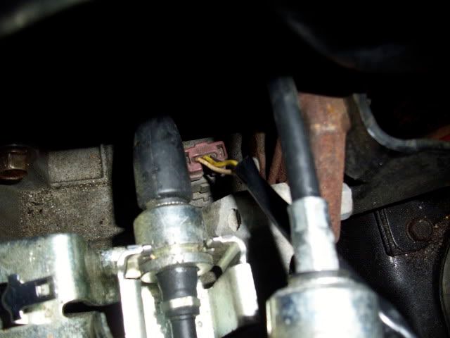
I drilled a small hole but I'm on my iPhone and pics are on my camera will post them asap. The wires are all solid colors, yellow white and black
03 ES 5spd--Rota torque gloss black 17x8 et. 35--Hankook Ventus V12 evo 235/45/17--D2 coilovers--DC Sports STB--Intake--Brembo calipers--Powerslot Rotors--Stoptech Pads--SS brakes lines--35% tint--5k heads & 5k fogs--Alpine headunit--Kicker 400w amp--Alphasonix sub
02 Mit. Galant 5 Spd -> 2010 Mit. Lancer Sportback 5 Spd -> (current) 2014 Mit Evo GSR 5 Spd
run1206's Rear Disc Tutorial
run1206's CF Hood Resurface Tutorial


Ok here are the pics...

03 ES 5spd--Rota torque gloss black 17x8 et. 35--Hankook Ventus V12 evo 235/45/17--D2 coilovers--DC Sports STB--Intake--Brembo calipers--Powerslot Rotors--Stoptech Pads--SS brakes lines--35% tint--5k heads & 5k fogs--Alpine headunit--Kicker 400w amp--Alphasonix sub
yeah, that was the sensor that came with my 2nd tranny, don't know the color codes with those, only thing i can think of is check the voltages with a voltmeter and review the voltage charts to determine which wire is signal and which is power (black is obviously ground)
02 Mit. Galant 5 Spd -> 2010 Mit. Lancer Sportback 5 Spd -> (current) 2014 Mit Evo GSR 5 Spd
run1206's Rear Disc Tutorial
run1206's CF Hood Resurface Tutorial
Dont be so sure about that.
Its hard to tell which way the connector is facing in the pic so I will explain it like this. If you remove the connector and look straight into the end of it with the little notch facing up, from left to right it should look like this
power, ground, signal.
this is according to the diagrams I have which have always been accurate for me.
99' Galant ESOriginally Posted by qnz
4G64/63T
AEM EMS
that's the only other way i knew how to determine which wire's which. The original speed sensor i had were the colors in the pic he posted, don't know why there's 2 different color code sets :?
02 Mit. Galant 5 Spd -> 2010 Mit. Lancer Sportback 5 Spd -> (current) 2014 Mit Evo GSR 5 Spd
run1206's Rear Disc Tutorial
run1206's CF Hood Resurface Tutorial


Alright this is pissin me off I've tried all possible combinations and still nothing works grrrrrr
03 ES 5spd--Rota torque gloss black 17x8 et. 35--Hankook Ventus V12 evo 235/45/17--D2 coilovers--DC Sports STB--Intake--Brembo calipers--Powerslot Rotors--Stoptech Pads--SS brakes lines--35% tint--5k heads & 5k fogs--Alpine headunit--Kicker 400w amp--Alphasonix sub
Where are you wiring it inside the car?
99' Galant ESOriginally Posted by qnz
4G64/63T
AEM EMS


I wired it up to these two...
And then on the speed sensor I grounded the center wire, and tried the outer two wires both ways, and still with no luck.
03 ES 5spd--Rota torque gloss black 17x8 et. 35--Hankook Ventus V12 evo 235/45/17--D2 coilovers--DC Sports STB--Intake--Brembo calipers--Powerslot Rotors--Stoptech Pads--SS brakes lines--35% tint--5k heads & 5k fogs--Alpine headunit--Kicker 400w amp--Alphasonix sub
Out of curiousity, why are those wires "3 & 4"???
When you read a connector diagram in the FSM, the # of the wires is from looking at them straight from inside the connector, so if anything the gray one would be 3 and the other would be 4.
Do you have a diagram showing which wire coming off the factory trans harness is for the stock auto speed sensor signal? I know the auto uses the internal sensor on 02-03 but still one of those wires has to be for signal that you can splice in under the hood. My diagrams show the speed sensor signal going from the sensor to the ecu and then to the cluster, but the connector in your pic is the one on the driver side near the ETACS, so im not sure whats going on.....
99' Galant ESOriginally Posted by qnz
4G64/63T
AEM EMS
Ok so now im angry that this isnt working for you....so I got ALL my diagrams out, try and stay with me, this hard without pics.
The wires you posted above in the pic of the large white connector are wrong.
Wire in #3 on that connector is the black wire with the white (maybe yellow? cant tell in the pic) stripe that is to the right of the wire you labeled 3 in your pic. The red wire next to that one is the correct #4 wire. That is your problem. I confirmed this with 2 different diagrams. You were just looking at it backwards, you were assuming wire position based on looking at the connector from the wire side head-on, when the FSM displays them as if you were looking into the end of the connector at the pin side. Hope this works out.
99' Galant ESOriginally Posted by qnz
4G64/63T
AEM EMS


I'll give it a shot tomorrow, thanks Brian! I'll let you know how it works out. So you're saying the black/white and red/blue are 3&4?
03 ES 5spd--Rota torque gloss black 17x8 et. 35--Hankook Ventus V12 evo 235/45/17--D2 coilovers--DC Sports STB--Intake--Brembo calipers--Powerslot Rotors--Stoptech Pads--SS brakes lines--35% tint--5k heads & 5k fogs--Alpine headunit--Kicker 400w amp--Alphasonix sub
Bookmarks