ok, I worked on this a few times and here's where I am at right now.
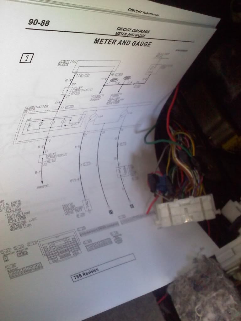
I was reviewing the wire diagram sheet and looked for distinct wires that are only on one side (to distinguish a reference where pin 1 is, thus located 3 and 4 afterwards).
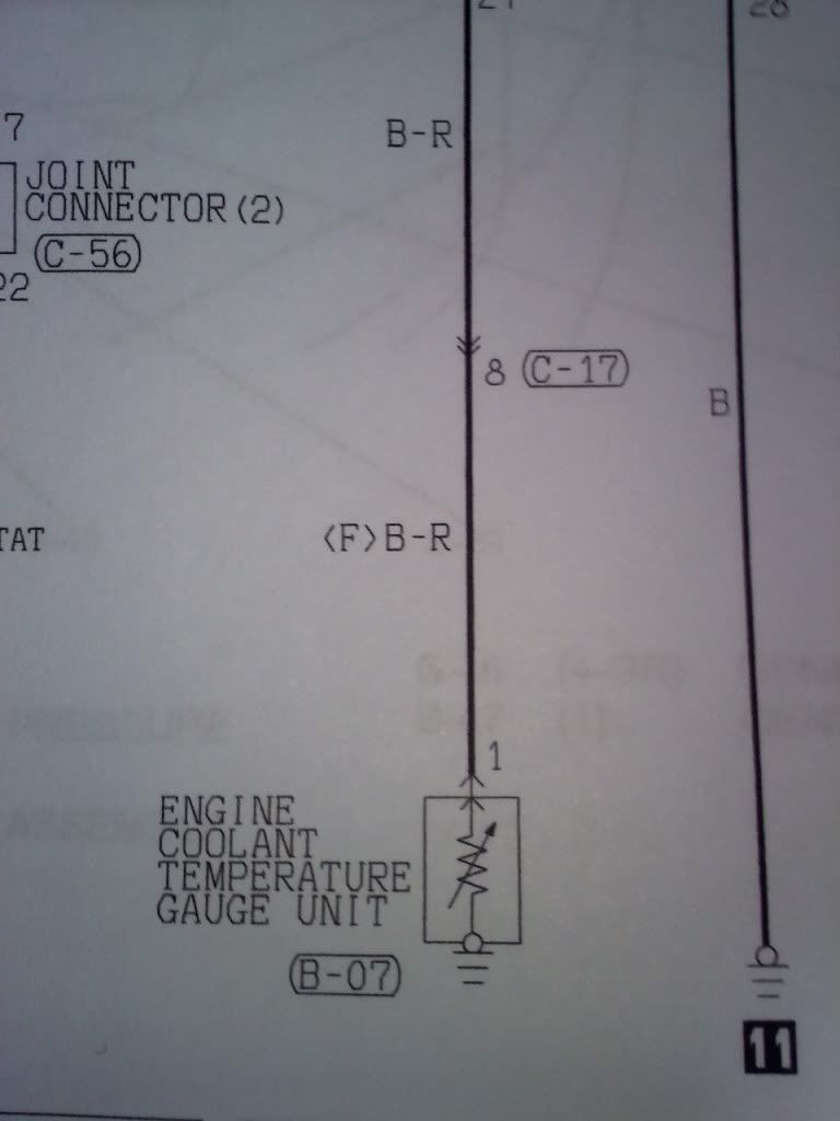
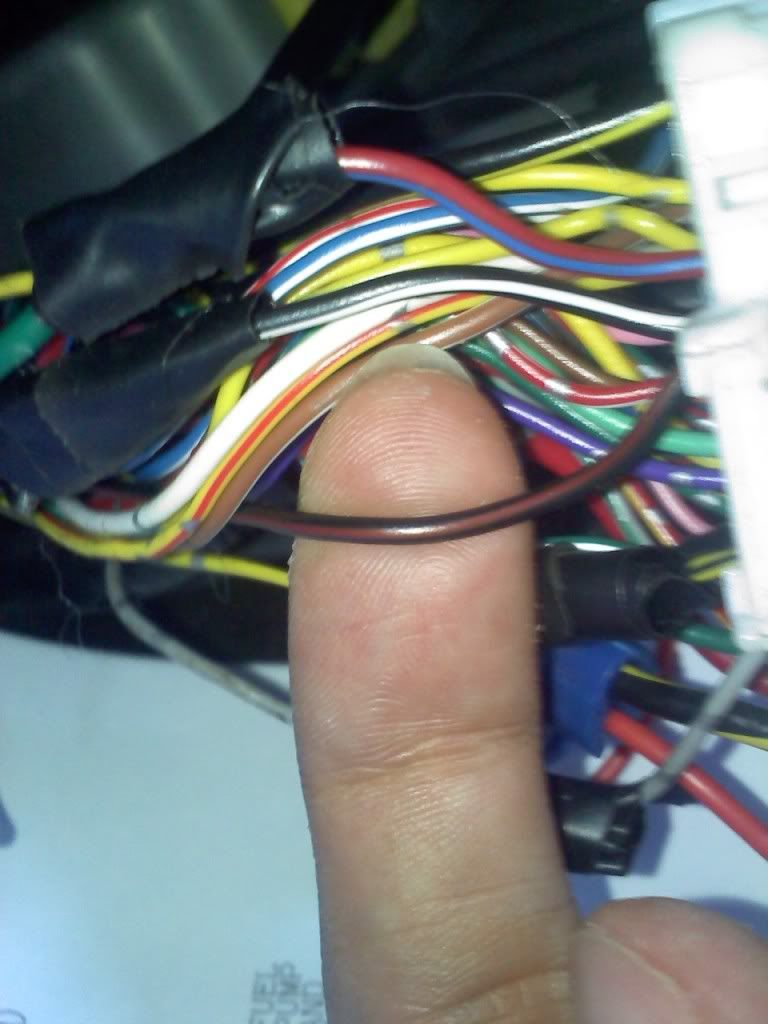
I used wire 8 as a reference; it's the wire for the engine coolant gauge. The color is Black and Red.
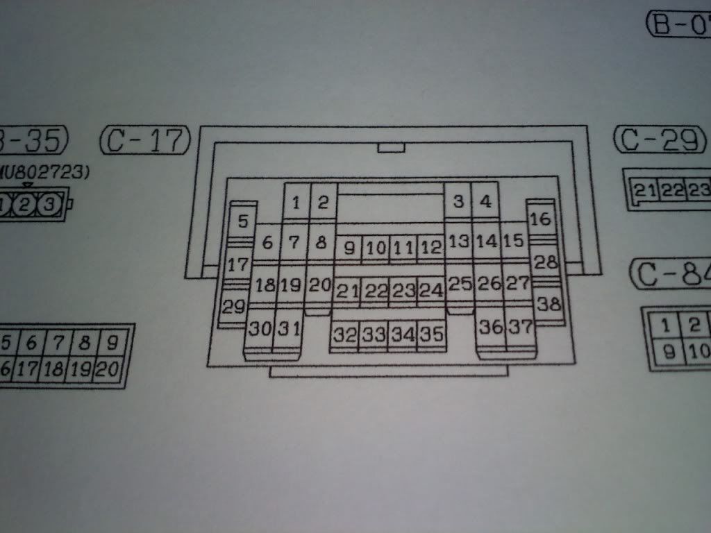
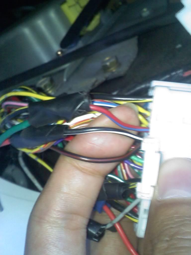
Looking at the harness (C-17) you find the one location for pin 8.
Using the diagram, and seeing pin 8 is the same side as pins 1 and 2.
(The other two wires on my finger are pins 1 and 2 according to the diagram, Red/Blue and Black/White. I've wired it to those wires and the speedo didn't work.)
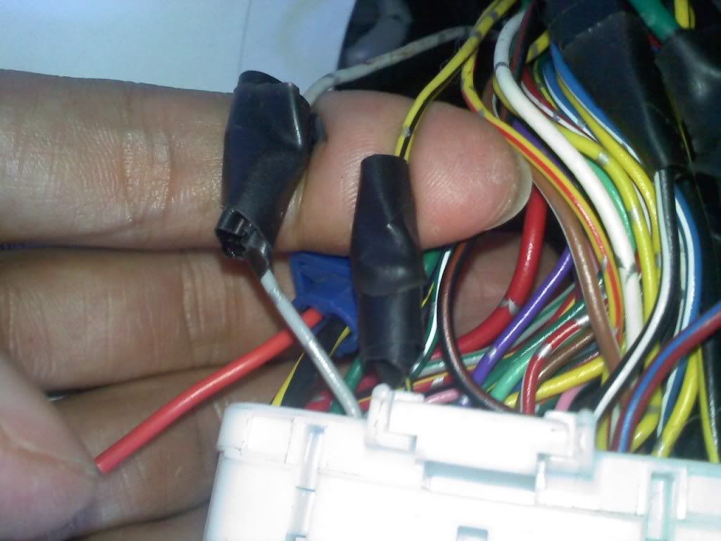
You would determine pins 3 and 4 on the other side of the harness, which the next picture shows, at least for my harness and diagram.
My pin 3 is Yellow/Black and my pin 4 is Gray/Silver, this was the same two wires that worked for the speedo when I drove to Florida, but unfortunately for some reason I've wired the same setup back and it does not work. This is why I mentioned I might have to disconnect the battery and reconnect, just to double check cuz that's what i did last time before it started working again.
One thing confusing me is the wires at the actual sensor are the same wire in the diagram, yet viewing the same wires on the harness you see different colors.
(Pins 3 and 4 in the diagram are Yellow/Black and Black/Blue respectively, yet pins 3 and 4 on the harness are Yellow/Black and Gray/Silver)
I'm gonna try to continue working on this after work tomorrow but this is where i'm at thus far.
 Log in
 Register


 2003 Mitsubishi Galant ES

 Reply With Quote






Bookmarks