The Galant Center - Powered by vBulletin

Thread: 1g cas in a 7g

Showing results 1 to 6 of 6
  1. #1
    TGC Regular phizzalot's Avatar
    Join Date
    04-25-2007
    Location
    Orlando/Ft. Luderdale ex {phizz2k}
    Posts
    727

    1g cas in a 7g

    [[[[[[[[[[-----------EDIT-----------]]]]]]]]]]]]]]]]]

    I had problems getting the car to idle with wiring i did previously and have figured it out now.

    Iam using a blk top Cas from a 93 NT eclipse.

    1g Eclipse Cas - 7g Galant Wiring from Dist

    Cas Pin 1 white wire (cam Sensor Signal) / 7g Galant brown-yellow from distributor
    Cas pin 2 blk wire (Crank Postion Signal) / (did not use) 7g Galant using original Crank Position Signal and wiring
    Cas pin 3 red wire (12v+ Positive) / 7g Galant Blk/Red Stripe wire Originally powered distributor.
    Cas pin 4 blk Ground / 7g Black Ground Distributor.

    I capped off the the other black wire and am idling without issue now.


    ((((Old wiring below did not keep the car idling)))

    Hello all its been a while but ive been working on some upgrades and had some questions about this swap.*
    So far I have the following.
    Cas Pin 1 white wire / 7g brown-yellow wire
    Cas pin 2 blk crank signal / 7g nothing
    Cas pin 3 red wire / 7g black-white wire
    Cas pin 4 blk ground / 7g black ground

    Iam left over with a 7g black-red wire not connected
    Also the black crank signal wire not connected.*

    I have the 7g crank sensor plugged into orignal plug and am using a 99 2g ecu.
    So does anyone know what to do with the blk-red wire from 7g dist and black signal wire from the 1gcas ?

    Here's a pic (haven't taped everything up yet)

    Last edited by phizzalot; 10-23-2012 at 09:51 AM
    ---||| 97Galant, E3 16G, Safc, 5spd,Drifter Body |||---

  2. #2
    Moderator mko's Avatar
    Join Date
    09-20-2007
    Location
    Sea Isle city, NJ
    Posts
    4,098
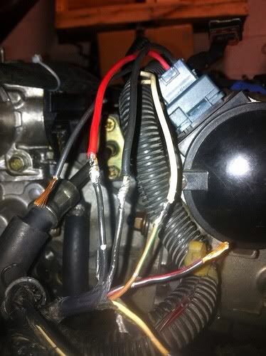
    Cap off the crank signal wire on the 1g CAS since youre not using it, and the black-red wire is a power supply for the Cam sensor in the distributor. The 7g distributor uses two power (+12V) wires - one for the transistor and one for the Cam sensor. Since you used one of them then just cap off the black-red wire.
    God created turbo lag to give the v8's a brief moment of hope.


    Build Thread

  3. #3
    TGC Regular phizzalot's Avatar
    Join Date
    04-25-2007
    Location
    Orlando/Ft. Luderdale ex {phizz2k}
    Posts
    727
    Thanks mko.
    I appreciate it.
    On to the coil on plug install next :)
    ---||| 97Galant, E3 16G, Safc, 5spd,Drifter Body |||---

  4. #4
    You are here entirely tooo much!! Galanttuner10's Avatar
    Join Date
    08-13-2008
    Location
    Waterbury, CT
    Posts
    3,331
    Phizz, post up how you do the COP as my only main snags seem to be on the power transistor wiring then withing in the connector to the coils.
    2014 Lancer Evo GSR
    1996 Galant S 5 Speed Turbo
    Need a Turbo rebuilt or upgraded--> http://www.thegalantcenter.org/showt...ebuild-Service

  5. #5
    TGC Regular phizzalot's Avatar
    Join Date
    04-25-2007
    Location
    Orlando/Ft. Luderdale ex {phizz2k}
    Posts
    727
    Will do, the cop setup seems prety simple as long as you begin with the correct coil. Iam using a tutorial from dsmtuners. Basically 3 wires from the cop will connect to the transistor. More info to come tonight..
    ---||| 97Galant, E3 16G, Safc, 5spd,Drifter Body |||---

  6. #6
    TGC Regular phizzalot's Avatar
    Join Date
    04-25-2007
    Location
    Orlando/Ft. Luderdale ex {phizz2k}
    Posts
    727
    Kinda late on this but wanted to update.
    After doing some additional research there seems to be a big debate about running a diy cop like the one iam doing without utilizing a aftermarket ignitor.(msd, Sparktech, aem) but I don't think iam going to run into any ignition issues as it only seems to occur for high power setup's..

    So I basically wired these in parallel and it leaves you with 3 wires to be connected to your power transistor.

    Cop wired up.


    On the power transistor
    Power Transistor Pin 1 <=> Bottom 3 Coil plug
    Power Transistor Pin 8 <=> Bottom 4 Coil Plug
    Power Transistor Pin 6 <=> Power Coil Top wires of 1 & 2

    If it doesn't start then I will switch Pin 1 & 6 and try again.
    Again iam using the link below as a basis of this setup
    http://www.dsmtuners.com/forums/arti...tall-pics.html

    This is all theory as I have not started the car and tested.
    Any comments are welcome.
    ---||| 97Galant, E3 16G, Safc, 5spd,Drifter Body |||---

Posting Rules

  • You may not post new threads
  • You may not post replies
  • You may not post attachments
  • You may not edit your posts
  •