 Log in
 Register
 Reply With Quote
Anyone?


whats up im looking for the 02 v6 distributor wiring diagram. i have already looked at the fsm(headache) but i was wondering if there is another diagram that explains it better any help will do thanks!!
STAY READY AND YOU WONT HAVE TO GET READY!!
Anyone?
STAY READY AND YOU WONT HAVE TO GET READY!!
The FSM has two diagrams for the ignition system, both basically the same though. What exactly are you looking for?
well it hard to explain i ended up trying to shorten and clean up the engine bay.i ended up cutting the distributor wires to shorten them but when i wired it back the car started but was running on a few cylinders than it shut off and hasent started since! it getting fuel and its turning over but just wont start its almost like there is no spark so im guess i wired it wrong so i wanna make sure i have it right here is a video i made not sure if it helps i feel like im making no sense
http://www.youtube.com/watch?v=pyFv4EL_LOc
Last edited by galant1983; 01-09-2013 at 05:54 PM
STAY READY AND YOU WONT HAVE TO GET READY!!


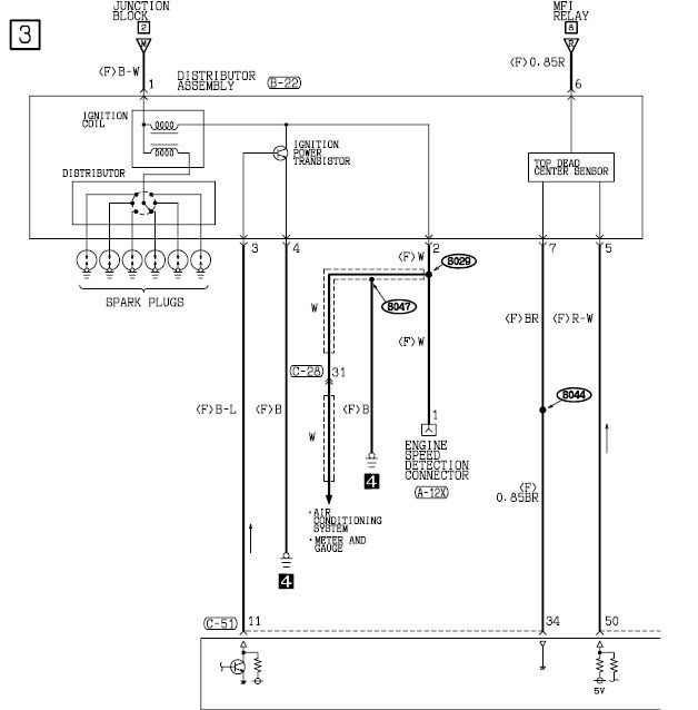
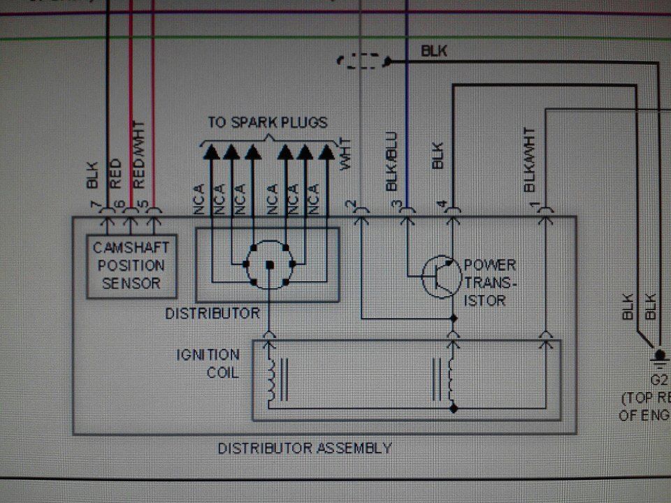
Here's a full one
mko is ur diagram for a 02 galant? i had another wirirng diagram but the colors where diff
STAY READY AND YOU WONT HAVE TO GET READY!!
First one is diff. year (i just saw it), the second one is correct
ok! wire #2(white) is my issue! where can i locate the engine speed detection connector(a12x) and air conditioning system/meter and gauge cuz it looks like the all connect together.i cant read diagrams for shit lol.
STAY READY AND YOU WONT HAVE TO GET READY!!


To clarify, the white wire is your tach output signal. it wouldn't alter the way your car runs whether it was connected or not. and I tried getting full screen captures of the diagrams but was unable to. the zoom causes them to distort badly when I tried to screen shot them.
'99 5-Speed GTZ: Forged 3.6L 6G74T 6764 E85
2017: 552whp/562wtq SBE on 19psi'02 Eclipse GT: 6G72 M/T-swapped Daily Driver'10 Endeavor: 6G75 AWD Family-mobile
so the white wire that comes off the distributor has no use???beside tach output?also there is a black wire that comes off the sensor that is between the belts?not sure if my video helped with what im asking
STAY READY AND YOU WONT HAVE TO GET READY!!
Distributor Connector is 7 pins
Pin #1 Black/White wire- 12v Ignition Switch Power supply
Pin #2 White wire - RPM Signal wire for Tach. This is a shielded wire (has thicker insulation and will have stranded wire wrapped around the white signal wire). Feeds to Pin #43 at PCM and goes back to the instrument cluster for Tach functions. This wire also feeds into the A/C system for its operation...still just a signal output wire though
Pin #3 Black/Blue wire - Signal output from PCM pin #11 for the ignition transistor operation.
Pin #4 Black wire - Ground wire, NEEDS to be on a good clean ground to complete good circuit operation
Pin #5 Red/White - Signal output wire from PCM pin #56 for Camshaft Position Sensor
Pin #6 Red wire - This is 12v MFI relay supplied power supply.
Pin #7 Black wire - Ground wire for camshafft position sensor, same stipulation as Pin #4 here
Black wire coming off the passenger side of the motor between the belts is your crank sensor wire and needs to be connected or it will not fire. The other Green/White wire with gray connector is for your knock sensor
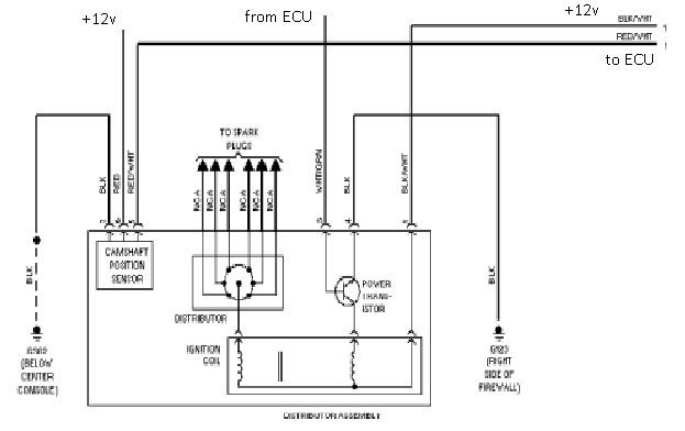
This diagram is incorrect for the Galant and should NOT be referenced or used. This is for the 03-05 Eclipse M/T models and wiring is way different
Originally Posted by mko

Nice! Now if this is wired wrong could I mess up the cap
STAY READY AND YOU WONT HAVE TO GET READY!!
Wow, you really must be full of yourself.
Now if you really paid attention you;d have seen that the pinout you posted is exactly matching the diagram i posted. Even the freaking colors are matching. Now they are not going to the same pins of the ECU thats a totally different matter.
The OP did not ask for what distributor wire goes where on the ECU, he asked for a distributor diagram OK. If you expect me to spoonfeed someone and break the whole thing down as if we were in elementary school then no I will not. You pick and chose what the useful information is from the entire picture.
I have the Galant distributor diagram on paper and the eclipse one on digital file, compared them and the distributor pinouts/colors are matching. I cropped it from the PDF instead of scanning it from the paper.
The distributor diagram is still standing as it is correct. You can go ahead and report this post again.
Good luck!!

hmm... More info the better IMO
Anyway, I was at the yard today and cut up a v6 distributor harness. I'll have pics up in a few.
Lancer/EvolutionX Rotor Glow Paint
6g74 Forged Engine w/ hx40 turbo
Eclipse GT 5 spd swapped
Rotor Glow Galant
Daily Galant
OZ Edition Eclipse
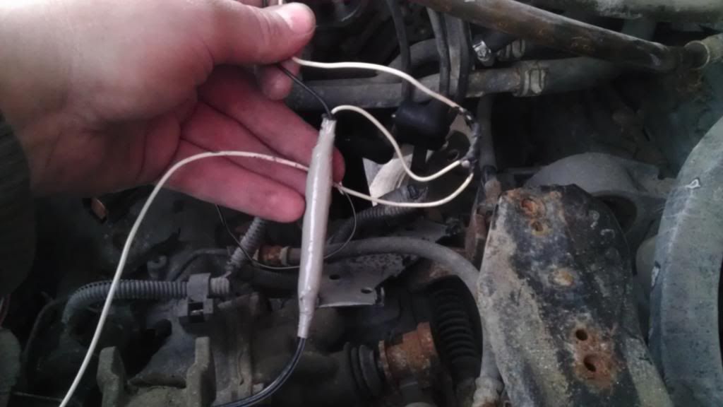
This is the white wire, pin #2 for the distributor harness:
You can see pin #2 splits off to 2 white wires, one goes into the engine harness and the other goes to another split. From there it connects to 2 black wires. The 1 black wire is a heavily insulated wire where the other black wire bolts right up to the intake manifold.
Also, pin #4 bolts up to the intake manifold.
If you want to me keep tracing, let me know.
Last edited by keith6110; 01-10-2013 at 05:37 PM
Lancer/EvolutionX Rotor Glow Paint
6g74 Forged Engine w/ hx40 turbo
Eclipse GT 5 spd swapped
Rotor Glow Galant
Daily Galant
OZ Edition Eclipse
Oh mko, dont be pissed because somebody called you on bad information you posted.
Please, by all means....do tell us all how your diagram helps the issue. Anybody who looked at it and was diagnosing a wiring issue on their galant would be plain screwed by one wire which if you paid attention to wiring there is a difference in a wire color as outlined in my first reply.
As a moderator YOU should give correct information and not half assed attempts. Dont want to "spoonfeed" correct information then dont post if you dont have it, plain and simple. If people wanted to keep getting screwe in circles, this is a perfect example of how and why they end up there.


Both of you need to settle the fuck down.
SPD_FRK - Yes mko is a moderator, but that doesn't give you the right to treat him like an asshat. I'm not always right, so deal with it in a grown up manner.
mko - If you believe your information is correct, and if someone doesn't, that doesn't give you the right to treat a member like an asshat. You are a moderator here. Act like one, even if the other man isn't.
Don't make me give you both a couple days vacation to cool off. I won't put up with it. Test me if you like.
If you post stupid and incorrect information, you will get red nuggets.
All information was clarified properly per the OP's request for a 2002 Galant diagram
Your point clear and understood, thank you
 Posting Rules

 1999 Mitsubishi Galant GTZ
 2002 Mitsubishi Eclipse GT
 1999 Mitsubishi Galant ES

Bookmarks