 Log in
 Register
 Reply With Quote
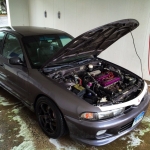 1997 Mitsubishi Galant DE
DOHCstunr was running the 1G ecu. now he is running speed density.
thats the man to talk to


Hey all,
I have an interesting challenge ahead of me. I am building a 7g Galant VR-4 using my recently acquired 95 Talon AWD as a donor. However I hung onto all my nifty DS-MAP (aka Jackal) speed density goodies from my old 1g DSM and want to run them in my new build. Problem is they only work with a 1g ECU. So I'm looking at putting a 1g ecu, and if necessary a 1g harness, into the Galant which will by economic necessity be running a 2g DSM motor.
Soooo... I'm trying to figure out how to make this work. I know the 1g harness fairly well but I am not familiar with the 2g wiring harness. I do know that the turbo motor swap into the Galant has been done by members on this site so the wiring for that leap has been covered (likely very little as they share so much else).
What I don't know is if with some creative rewiring it becomes possible to run a 1g ECU on the 2g (or Galant) wiring harness without major errors. If not, I'll need to track down any wiring issues with running the 1g harness in the 2g such that all the gauges work properly. A lot of this may just come down to hours of tracing wiring diagrams but if anyone has input I'd really appreciate it.
Last edited by eclipsh; 03-05-2009 at 08:34 AM


DOHCstunr was running the 1G ecu. now he is running speed density.
thats the man to talk to
"DSM's, making people mechanics since 1985"
Originally Posted by polishmafia
Cool, thanks :)
OK, so I went and picked up my 94 Galant ES today along with a 1g EPROM ECU (found it in the first awd car I checked!). After a PM back from DOHCStunr I should be able to just wire in the 1g ECU plugs, run wires for a few extra bits and be good to go. I'll take some pictures and post them up before I start tearing the car down.
sweet, keep us posted!
"DSM's, making people mechanics since 1985"
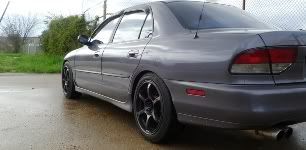
Here are some pictures of the Galant as it was yesterday morning. The paint is peeling a bit on the hood and the rear of the roof but is otherwise in good shape. I'll need a new windshield as well as it has numerous cracks. The driver's rear window had already been picked at the yard so I found another one and slipped it into place but haven't finished the installation. I couldn't find a tinted one so I'll get the clear one I picked matched to the rest later on.
The interior is better than I remembered it being. Dirty as hell but nothing is torn up besides the passenger's sun visor and the right airbag cover is peeling a way slightly.
The body is actually very clean save one small dent at the base of the driver's front fender and door that I may be able to straighten. Unfortunately the front bumper cover is falling apart along the bottom so it will have to be replaced. I'm hoping to find a JDM VR-4 cover.
The engine bay actually looked very good. I didn't see any oil leaks at all. With a fresh battery and some gas it fired right up in the junk yard. Unfortunately the transmission is shot, reverse doesn't work at all. Unless someone needs a core for a rebuild I'll be taking it to the scrap yard.
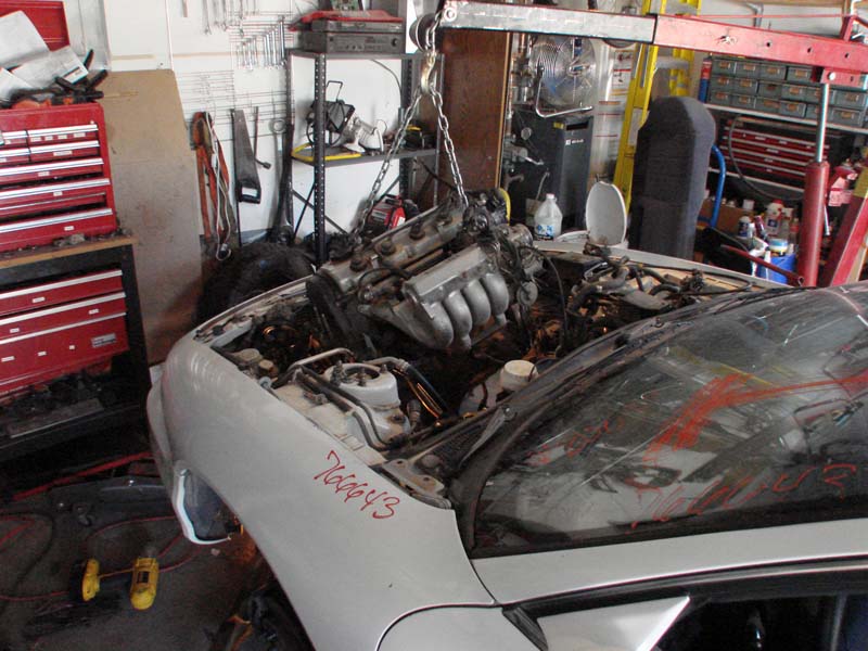
After a few hours of work I got the engine ready to pull out and quickly found that it couldn't come out the topside with the tranny attached. I pulled the front cross brace, dropped the engine/tranny to the floor and separated them, then pulled the engine out the top and set it on blocks.

Last edited by eclipsh; 02-25-2009 at 09:04 AM
Looks like I'll be doing some repair on the ECU I found. I'll see how bad the damage is. If it is just surface corrosion I'll clean it up, stick some new capacitors in and socket the EPROM myself. If it looks too bad I'll just ship it off to Steve on DSM Tuners.
I'm almost done pulling the engine wiring harness out to rewire it too. I decided it'll be much cleaner and easier if I can just lay it out on the floor, pull the A/T components I don't need and wire in the new parts I do need. I still need to find some good factory wiring diagrams for the 7GA.
So I spent today working on a diagram for the 7ga to 1g ECU setup. Read not much fun at all but a lot less dirty. I'm still trying to figure out several points, i.e. the bold areas
7g PIN Function 1g PIN
1 #1 INJECTOR 51
2 #3 INJECTOR 60
3 FAN MOTOR RELAY N/A
4 IAC (CLOSED)
5 IAC (VALVE #1)
6 EGR SLND 53
7 TCU N/A
8 FUEL PUMP RELAY 56
9 PURGE CONTROL SLND 62
10 IGNITION POWER TRANSISTOR - part of the distributor, replaced with 1g components, cap off.
11 A/C INTERMEDIATE SWITCH
12 POWER – KOEO (key on engine on) - 102
13 GROUND - joins with 26, grounds MPI relay above.
14 #2 INJECTOR 52
15 #4 INJECTOR 61
16 FAN LOW
17 IAC (OPEN)
18 IAC (VALVE #2)
19 MAS RESET (91+) 6
22 A/C CLUTCH 65
23 IGNITION POWER TRANSISTOR - Cap off
24 ELECTRIC LOAD SWITCH (LIGHTING ON/OFF), - cap off
25 POWER – KOEO - 107
26 GROUND - joins pin 13
34 IGNITION TIMING ADJ. 12
HEATED O2 FRONT - cap
36 CEL WARNING LAMP 64
37 POWER STEERING SWITCH 5
45 A/C SWITCH - cap
51 IGNITION SWITCH START 108
52 INTAKE AIR TEMP 8
53 EGR TEMP SENSOR 15
55 HEATED O2 REAR
56 HEATED O2 FRONT
60 BATTERY BACKUP 103
61 SENSOR +5V to TPS? 23
63 ENGINE COOLANT TEMP 20
64 TPS 19
65 BAROMETER 16
66 VEHICLE SPEED 18
67 CLOSED THROTTLE/IDLE 14
68 CAMSHAFT POSITION - goes to distributor
69 CRANKSHAFT POSITION - distributor
70 VOLUME AIRFLOW 10
71 PARK/NEUTRAL (A/T)
72 COOLANT TEMP SWITCH (KOEO)
Now I know a few of these won't have connections such as the O2 sensor heaters and the fan switches (which I will wire to a temp sensor instead). The IAC connections are one problem. I'll also need to figure out the MPI circuit and ignition power transistor wires.
The 1G pins I don't have connections to yet are:
102 & 107 12V from MPI relay pins 4&5 - pin 12 or 25
105 wastegate solenoid output - ignore
109 Tach input, wire this from power transistor
110 Ignition switch (IG1) input, pin 8?
54 ignition trigger 1&4 - wiring to power transistor
55 ignition trigger 2&3 - wiring to power transistor
56 MPI relay pin 7 - taken care of if I use 5 pin relay for fuel pump
57 fuel pressure solenoid - I will ignore this one
58 ISC coil A1
59 ISC coil A2
63 & 66 MPI relay pin 8, ground for 4 wire relay
67 ISC coil B1
68 ISC coil B2
3 boost gauge - will need wires run or ignore it
4 Oxygen sensor input (will wire in my WBO2 so no worries there)
7 A/C coolant temp switch
9 knock sensor (will have to run wires)
11 ABS control unit output don't know if I need this as the 7g ABS doesn't seem to utilize it.
13 fuel pump voltage monitor input jumper from fuel pump relay? Is it necessary?
17, 24 sensors ground - which sensors? Does it matter?
21 crank angle sensor part of CAS wiring?
22 TDC sensor
Last edited by eclipsh; 02-26-2009 at 10:53 AM
Looking into the MPI relay issue I'm not sure if I need to track one down in a DSM or if I can run without one. I'd be a little concerned about the extra power running through the ECU so I'll look into exactly what wiring will need to happen. I really need some good factory wiring diagrams for the entire 7g. It'd be good to see what wires I'd be tapping into for the relay or if there is already an MPI in the 7g that I just don't know about.

Well one option for the IAC is to just block it off with a plate and wipe the CEL for it if there is one. Wish I could be of more help.
RIP
1995 7G 4G64 / 63T DOHC Turbo
Part Out Coming Soon
In search of 2G 3000GT VR4
Daily driving
Dat '08 Cobalt Coupe
Thanks for all the help so far :) I have read enough about the IAC that I think it prudent to leave it there. Apparently it does more than just adjust the idle.
It is just four wires (trying to convince myself to trace them and figure out which does what on the 1g.)
EDIT: OK, so pin 56 on the 1g ecu ground the portion of the MPI for the fuel pump. So with a standard DSM fuel pump rewire and relay I can bypass the MPI for that.
The MPI has 10 pins so...
1 = empty
2 = power to fuel pump
3 = ignition power for fuel pump
4 & 5 send power to pin 107 via the main fusible link when the relay is triggered. Pin 4 also sends power further down the line to various sensors, actuators etc.
6 = grounds 9, also looks to be second ground for fuel pump relay (likely to keep the pump running while the car is being cranked).
7 = fuel pump relay ground, pin 56 ECU
8 = grounds 10, the relay for 4 & 5 when 63 and/or 66 authorize it. Has a diode limiting flow from returning to 10 from 8.
9 = feed from starter relay, also routes to pin 108 of ecu
10 = Main Fusible Link 1 (ie, the battery)
So basically it is one 5 pin relay with two triggers and one 4 pin relay with a diode.
Last edited by eclipsh; 02-26-2009 at 01:05 AM


I gave up on the IAC after a couple fried 1g ECU's.
I just got a blockoff plate and eliminated the FIAV and IAC.
No CEL's of course. and it idles perfect w/ ds-map.
takes just a little getting used to but its really no biggie.
______________________________

1994 Galant GS-Turbo
Made some updates to the wiring lists. I'm also wondering where exactly in the wiring I'll want to put the resistor pack for the injectors (can't think of the right name for it, too tired).
What else am I missing?
thats the general idea.
remember the ecu opens injectors by grounding the circuit.
the multi color wires on the injector connectors are the ground, thewire thats the same color onevery injector is your 12v source.
cut the 13v wire,run one wire from each injector to merge into one wire that will be wired into the resistor pack, then run the 4 low impedance wires bsck to the injectors.
then conceal the wiring within the harness.
______________________________
1994 Galant GS-Turbo
OK, looking at another set of wiring diagrams for the Galant it looks like it does have an MPI relay which does the same things as the one in the 1g DSM. So i just have to run the correct wires and I'm good to go.
I've begun pulling the pins out of the 1g ECU harness connectors but I left the ones for the power transistor in place. I'll throw together a complete diagram when I'm done with all this and post it up on here.

ISC AND THROTTLE BODY
Take the 1g/2g ISC the pins are as follows staring at the ISC itself.
Above pin 2 is the little clip where the connector locks in.
1 2 3
4 5 6
With that said, remove the connector from the 4g64 IAC, and remove the throttle body from the car. Install the 1g or 2g Throttle body and connect the wires from the 4g64 IAC connector to the 1g/2g ISC like this:
On the 1g ISC connect both pins 2 and 5 to the single red or white wire from the resistor pack. This is power to the ISC.
Pin 1 of the ISC goes to the Blue/Yellow stripe wire on the 4g64 IAC connector
Pin 3 of the ISC goes to Green/Black
Pin 4 of the ISC goes to White
Pin 6 of the ISC goes to Green
Awesome, thanks! I'll cross reference that with the 1g wiring at the ECU and see what I come up with. Unfortunately I'm stuck with the 2g TB right now or trying to switch over to the Galant's TB. I haven't dug into the 2nd option yet.
i believe the wiring is the same
Well I went out of town Friday and Saturday. Thursday I pulled the rear subframe, suspension, gas tank and exhaust out. I also cut the body and popped the rear subframe bolts out to replace them with the longer awd bolts then drilled holes right behind the back seat hinges to drop bolts in for the front of the subframe. I got a bit of the wiring for the harness done too.
Today I got back to work on the harness and got a lot done. I pulled all the A/T components out and added the wiring for the coil pack/transistor, and resistor pack for the injectors. I still need to wire in a reverse light switch, knock sensor and cam sensor. I also need to wire in the ISC motor and eventually the fans. Pins on the 1g ECU that are still open are:
110 - ignition switch
63 mpi control relay
67-8, 58-9 for ISC
13 control relay fuel pump
1 self diagnostic (pin 42 or 43 of Galant ECU, haven't checked yet)
2 diagnostics
3 turbo gauge - will need to run this wire and fit 2g gauges into dash still. I also need to look into wiring the oil pressure gauge and all the other gauges for that matter... I haven't looked at the connectors yet to see if they'll match.
4 - O2 sensor
7 A/C Switch
21 CAS
22 TDC sensor
9 knock sensor
I also took care of the repairs to my ECU and added a socket for the EPROM. Doing that took a good chunk of the morning but it is done.
I will also need to add the wires for my MAP sensor and IAT sensor to run speed density and get my wideband harness added into the mix.
Boy I hope I haven't screwed anything up yet... Tracking down wiring mistakes in this hodgepodge will be a pain.:smt073
Tomorrow I'll get started tearing down the Talon...
Last edited by eclipsh; 03-02-2009 at 12:00 AM
I pray that you are photo-documenting this.
Every step you take deserves a photo.
Keep it up man, i'm stoked to see what you can churn out.
______________________________
1994 Galant GS-Turbo
 Posting Rules


Bookmarks